The Universal Device Management Interface (UDMI) provides high-level specifications for the management and operation of physical Internet of Things systems. This data is usually exchanged with cloud entities that can maintain "digital twins" or "shadow devices" in the cloud. It is nominally used with Googe's Cloud IoT Core, and as an architecture, it can be applied to any data set or hosting setup. In addition, the architecture provides provisions for basic telemetry ingestion, such as the flow of data points from IoT devices.
In this tutorial we'll see step by step how to implement UDMI using the connectors Framework.
Cloud Setup
Create the registry
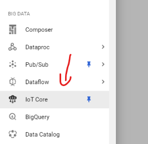
- Go to the GCP console from the left side navigation pane find the Big Data section then choose Iot Core service.
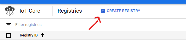
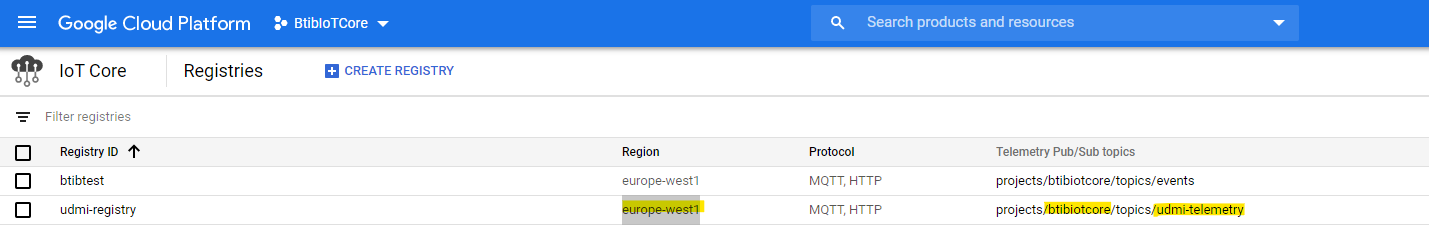
- Create a device registry.
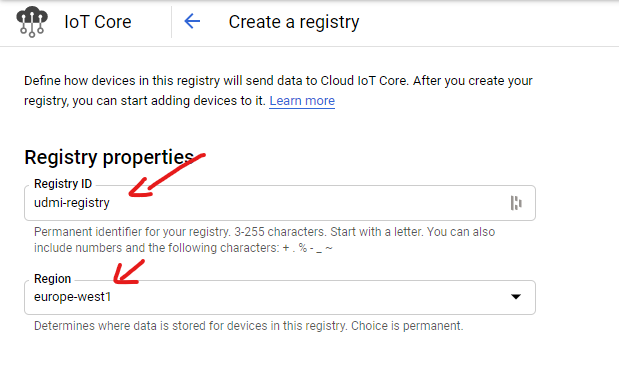
- Give your registry a name and select the most suited region for you.
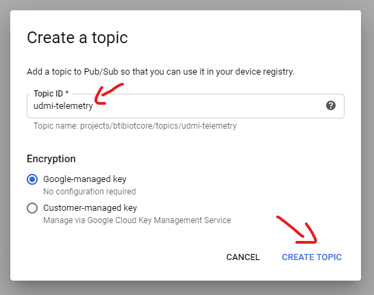
- On the PubSUb section create a new topic where events will be published by IoT Core devices.
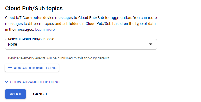
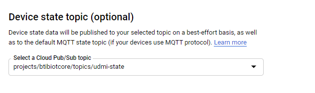
- Add another topic for device state. Click on show advanced config
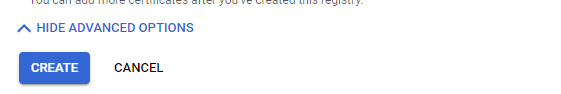
- Then hit create
Create a service account
- From the left navigation bar select IAM & Admin
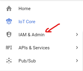
- Then Service Accounts
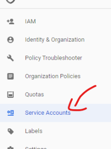
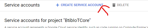
- And hit create
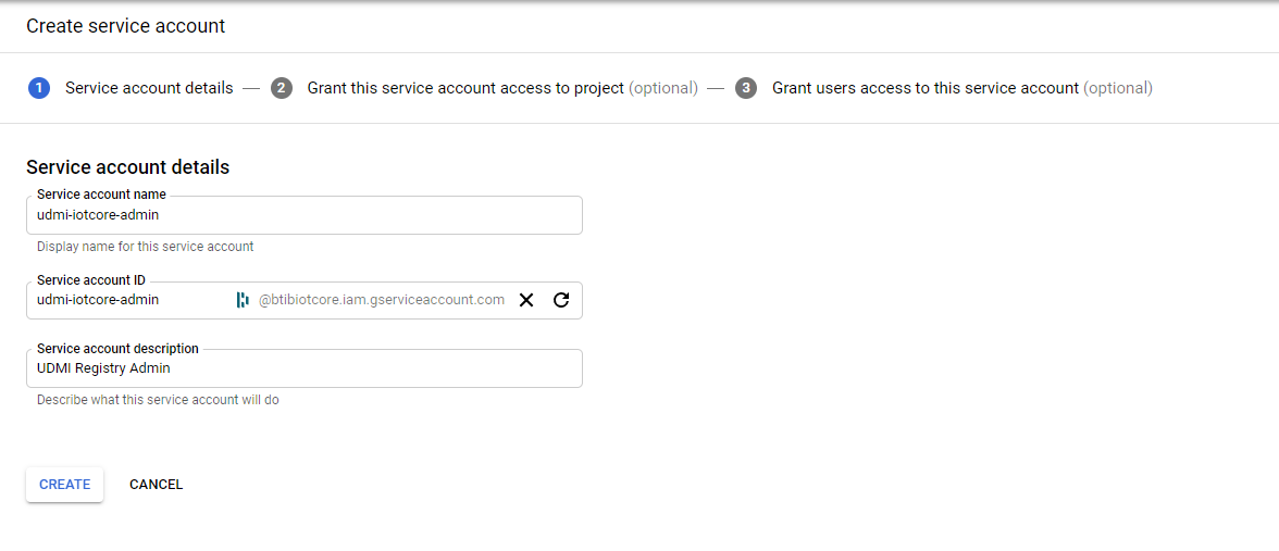
- Then give your service account a name and a description.
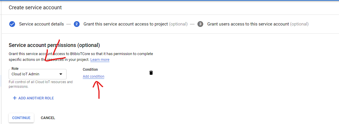
- Choose the Cloud IoT Admin (you can add conditions to give permission on a specific resources recommended). and click on Continue.
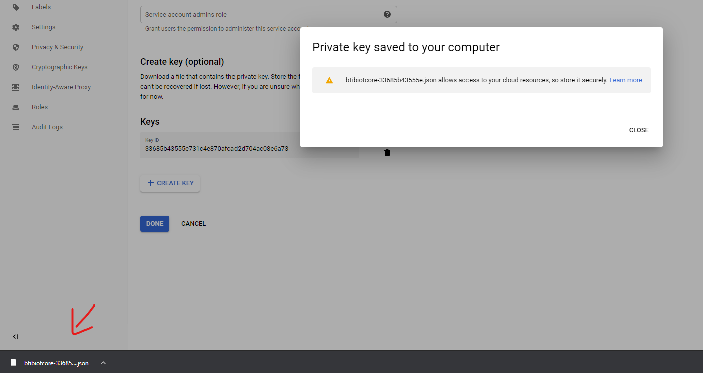
- Create a key and choose json format then hit Create.
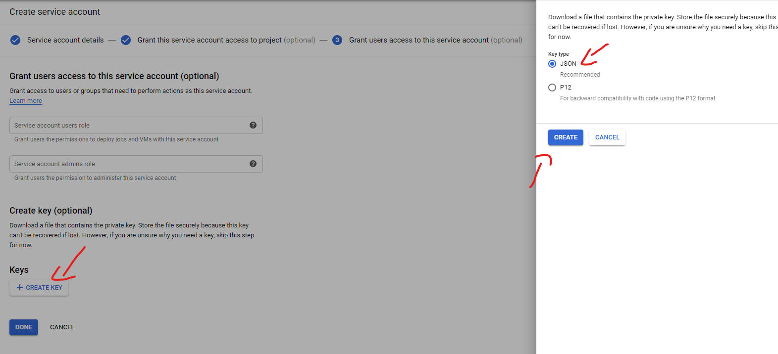
- A json file will be dwonloaded containing the access key for this service account save it we will need it later.
8. Type this commands to generate a public/private keys.
openssl req -x509 -newkey rsa:2048 -keyout rsa_private.pem -nodes -days 36500 -out rsa_cert.pem -subj "/CN=unused"
And
openssl pkcs8 -topk8 -inform PEM -outform DER -in rsa_private.pem -nocrypt > rsa_private_pkcs8
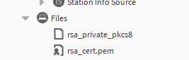
These commands will generate 3 files we will need 2 of them:
- rsa_cert.pem.
- rsa_private_pkcs8.
Connector Setup
Connection setup
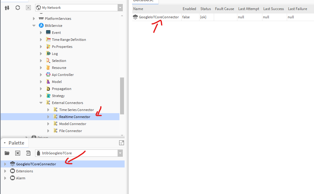
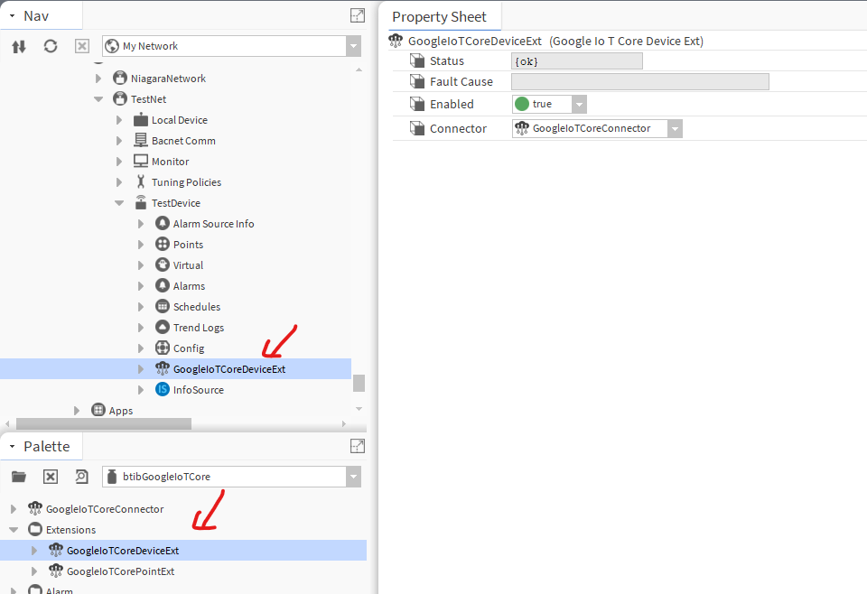
- Go to the GoogleIotCore palette and drag and drop the connector to BtibService → ExterbalConnectors → RealtimeConnector
- Copy the keys to your station
- Fill the connection information
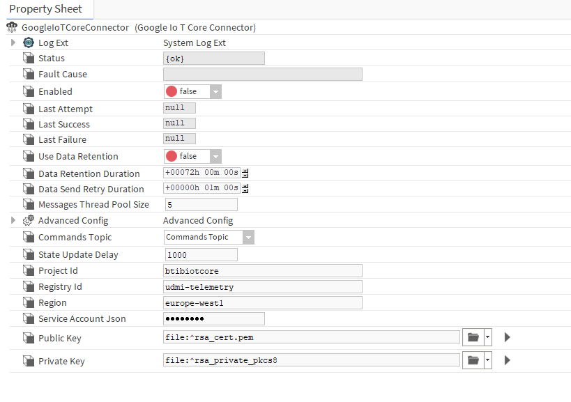
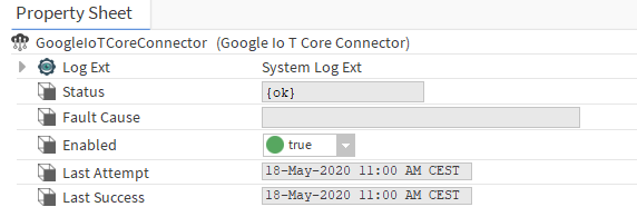
- Enable the connector you should see the last attempt and last success values populated.
UDMI Setup
UDMI specification uses custom format for messages exchanged between the cloud and the device
Device Telemetry schema:
- Schema https://github.com/faucetsdn/daq/blob/master/schemas/udmi/pointset.json
Example:
{
  "version": 1,
  "timestamp": "2018-08-26T21:39:29.364Z",
  "points": {
    "reading_value": {
      "present_value": 21.30108642578125
    }
  }
}
Device State:
- Schema https://github.com/faucetsdn/daq/blob/master/schemas/udmi/state.json
Example:
{
  "version": 1,
  "timestamp": "2018-08-26T21:39:29.364Z",
  "system": {
    "make_model": "ACME Bird Trap",
    "firmware": {
      "version": "3.2a"
    },
    "last_config": "2018-08-26T21:49:29.364Z",
    "operational": true,
    "statuses": {
      "base_system": {
        "message": "Tickity Boo",
        "category": "device.state.com",
        "timestamp": "2018-08-26T21:39:30.364Z",
        "level": 600
      }
    }
  },
  "pointset": {
    "points": {
      "return_air_temperature_sensor": {
        "units": "Celsius",
        "status": {
          "message": "Invalid sample time",
          "category": "device.config.validate",
          "timestamp": "2018-08-26T21:39:28.364Z",
          "level": 800
        }
      }
    }
  }
}
Device Commands
- Schema https://github.com/faucetsdn/daq/blob/master/schemas/udmi/config.json
Example:
{
  "version": 1,
  "timestamp": "2018-08-26T21:39:29.364Z",
  "system": {
    "min_loglevel": 500
  },
  "gateway": {
    "devices": {
      "AHU-123": {
		"protocol": "bacnet",
        "local_id": "327412"
      }
    }
  },
  "pointset": {
    "points": {
      "nexus_sensor": {
        "fix_value": 21.1
      }
    }
  }
}
- Go to the advanced config slot on the connector.
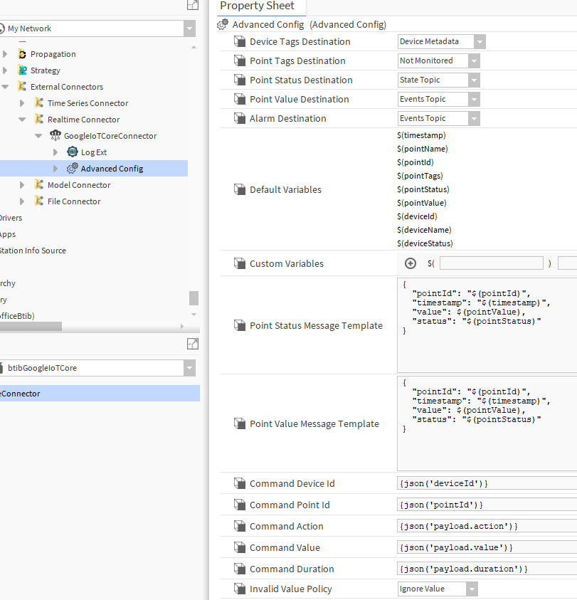
On the message value template put the udmi template below
{
  "version": 1,
  "timestamp": "$(timestamp)",
  "points": {
    "$(pointId)": {
      "present_value": $(pointValue)
    }
  }
}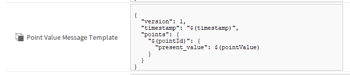
On the state template use.
{
  "version": 1,
  "timestamp": "$(timestamp)",
  "system": {
    "make_model": "$(deviceName)",
    "firmware": {
      "version": "1"
    },
    "statuses": {
      "base_system": {
        "message": "$(deviceStatus)",
        "category": "device.state",
        "timestamp": "$(timestamp)"
      }
    }
  },
  "pointset": {
    "points": {
      "$(pointId)": {
        "status": {
          "message": "$(pointStatus)",
          "category": "point.state",
          "timestamp": "$(timestamp)"
        }
      }
    }
  }
}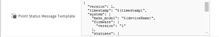
For commands we use this template and SFormat to extract the json information needed.
{
  "version": 1,
  "pointset": {
    "points": {
      "nexus_sensor": {
        "value": 21.1
      }
    }
  }
}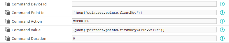
Testing configuration
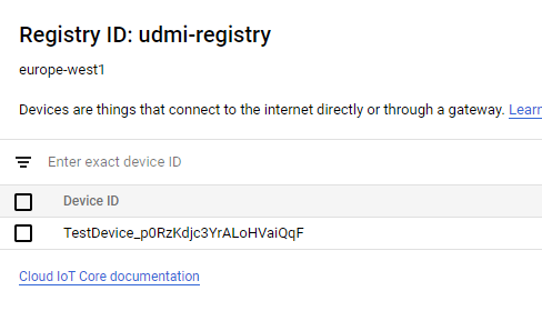
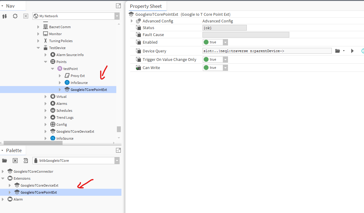
- Create a new device and add a device ext.
- On the device registry verify that the device provisioned successfully.
- Create a point and add a point ext.
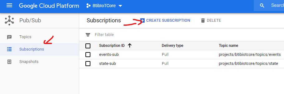
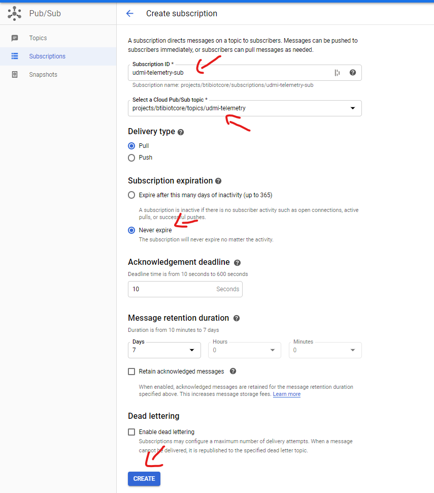
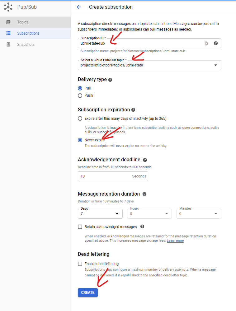
- To view messages we should create a subscription to the telemetry and state topics. On the Google console go to the pubsub service → subscription → create.
- Give the subscription a name then choose the telemetry topic and click on Create.
- Do the same for the state topic subscription
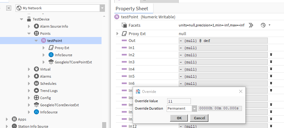
- Now go to the Niagara point and change the value and the state.
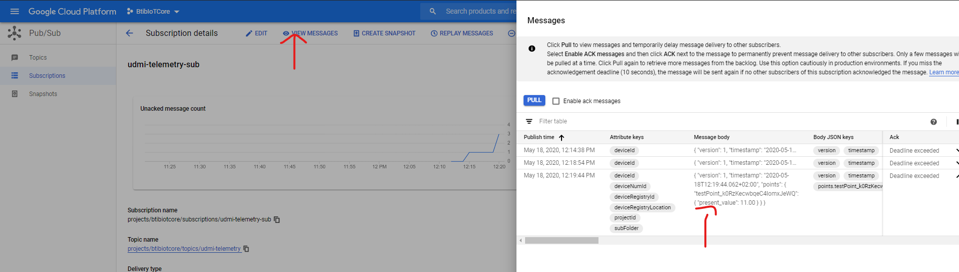
- On the telemetry subscription you should see your message.
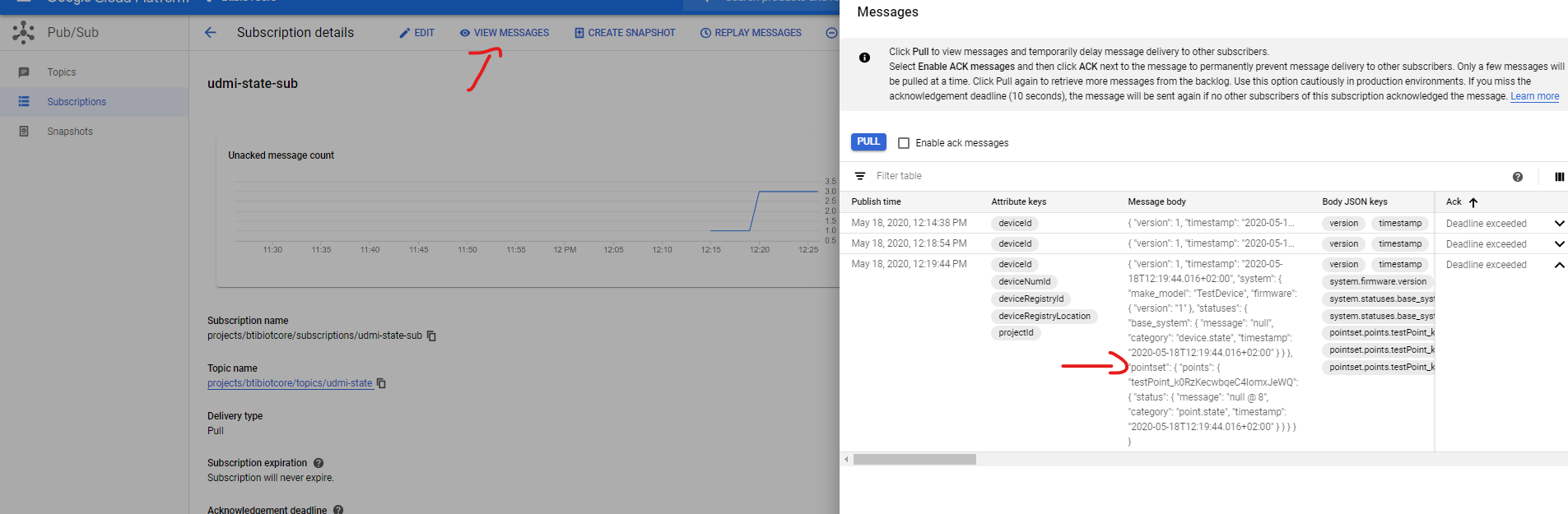
- The same for the state subscription
Congratulations you finished the tutorial for more information check the connector documentation.